← Selected work

01 · Wearable rehabilitation robotics · modeling + evaluation

M.Sc. thesis · 2026

A wearable tendon-driven finger actuator, built and evaluated for neuro­rehabilitation tasks.

An M.Sc. engineering feasibility study spanning simplified mechanics, repeatable benchtop experiments, and an on-hand wearable prototype.

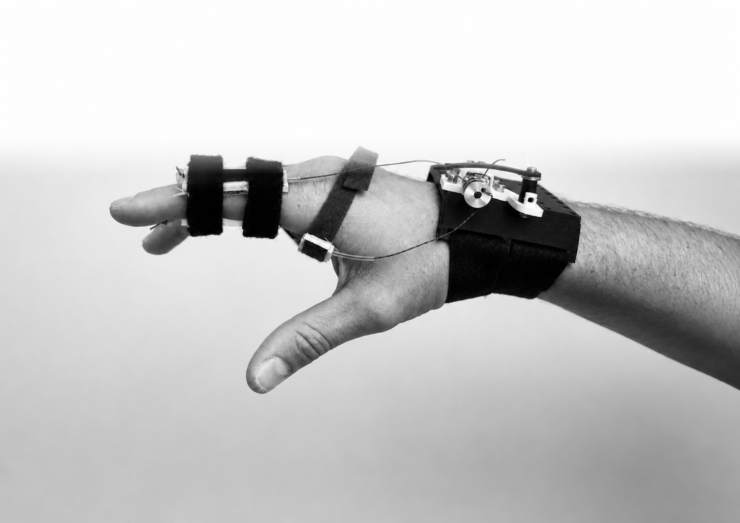
Finished wearable soft-finger actuator on a hand

Role

M.Sc. thesis · 2026

What I built

Built reduced-order models for finger kinematics, tendon routing, passive torque, leverage, stroke, and tension.

Selected evidence

1,000 / 1,000 rigid-fixture cycles

The problem

The thesis turns an assistive-device concept into a working system of tendon routing, mechanics, control, and repeatable measurement. The final prototype moved from rigid benchtop tests to trials on the hand.

Technical ownership

  1. 01Built reduced-order models for finger kinematics, tendon routing, passive torque, leverage, stroke, and tension.
  2. 02Used Python sweeps to screen stiffness and geometry choices before hardware iteration.
  3. 03Programmed the final Arduino Uno motor/encoder control loop in C and built Python host and analysis tooling.
  4. 04Designed a benchtop validation loop around force, displacement, motion tracking, repeatability, and model error.
  5. 05Integrated the wrist unit, tendon path, and finger interface into a wearable prototype for on-hand testing.
  6. 06Supervised three student interns contributing to fixture, control, computer-vision, and sensing work.

System architecture

Reduced-order routing model → Arduino Uno motor/encoder control in C → camera and encoder measurement.

Evidence + outcome

1,000 / 1,000 rigid-fixture cycles97.5% of 49.93° comparatorOn-hand wearable testing3 student interns supervised

Tools + systems

PythonOpenCVArduino UnoC motor + encoder controlFDM prototypes
Case study

The decisions behind the final prototype.

The model did not hand me a finished design. I used it to choose what to build next, measured the drive and load sides separately, and changed the routing when the hardware disagreed.

Where it started

Before I modeled the mechanism, I spoke with clinicians and patients about rehabilitation needs and the practical limits of existing devices. Those conversations set the direction for a wearable design that could be tested on the hand.

Measurement loop

The rig made lost motion visible.

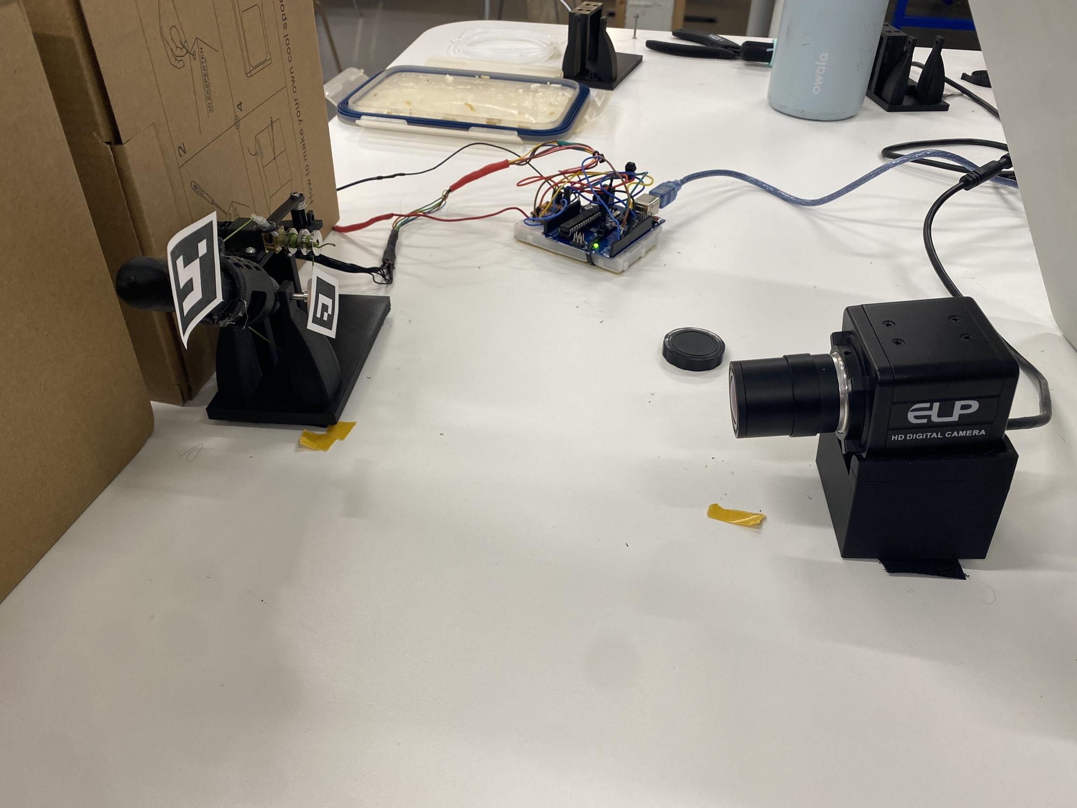
The Arduino commanded the motor while the encoder measured the drive side and the camera measured the finger side. That separation mattered. Motor motion alone could not show whether the tendon path actually transferred motion to the load.

Thesis test setup with finger fixture, Arduino controller, encoder wiring, and camera measurement system
The final measurement setup connected motor control, encoder feedback, and camera-side motion tracking.

Control architecture

The controller changed as the hardware got faster.

The first rig could wait for the camera. The wearable could not, so timing moved into firmware and vision became a slower correction channel.

  1. 01

    Visual guidance

    The webcam measured angle online between small encoder jogs. Each move ended with a pause and another measurement.

    Useful for calibration, too slow for tapping
  2. 02

    Firmware timing

    A half-cosine trajectory ran on the Arduino while encoder and velocity feedback set motor PWM. The camera moved offline.

    Deterministic motion on the rigid fixture
  3. 03

    Two-layer control

    The encoder handled the fast inner loop. A bounded camera loop near 50 Hz trimmed the reference as the wearable load path changed.

    Fast motor control with load-side correction

Route A to Route B

A small routing change came from the model.

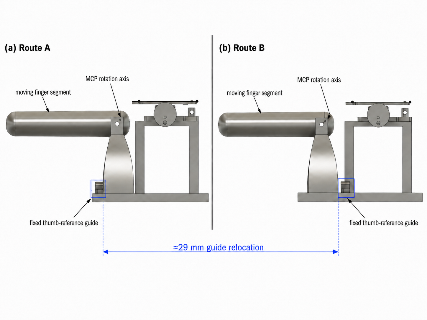
A reduced-order screen pointed toward moving the fixed guide. I used that result to revise the routing and chose a 29 mm shift near the high end of the screened range.

Side-by-side diagram comparing the original Route A tendon guide with the revised Route B guide position
Route B moved the fixed guide by about 29 mm to change the tendon leverage and available excursion.

Rigid validation

The revised setup completed all 1,000 commanded cycles.

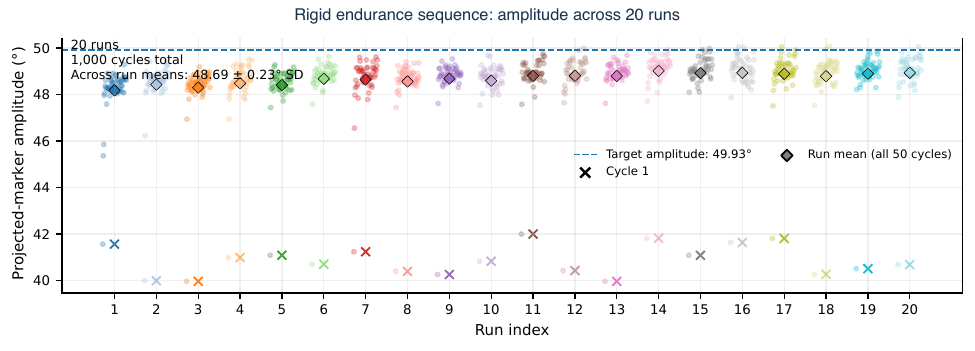
The endurance sequence ran 20 consecutive sets of 50 cycles without changing the installation or configuration. Across the run means, measured excursion reached 97.5% of the 49.93 degree engineering reference, with about 0.26% mean period error.

Plot of projected marker amplitude across twenty rigid-fixture endurance runs totaling one thousand cycles
Twenty runs, fifty commanded cycles per run. The first-cycle points also show why inspecting individual cycles mattered.

Wearable evolution

How the wearable changed.

The hand interface went through rings, straps, a failed resin transmission, and removable guides before the final build.

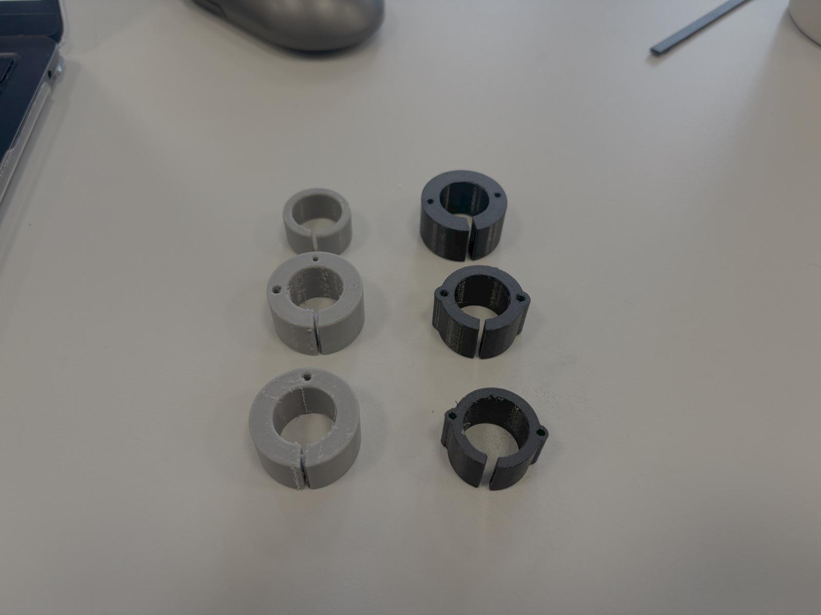
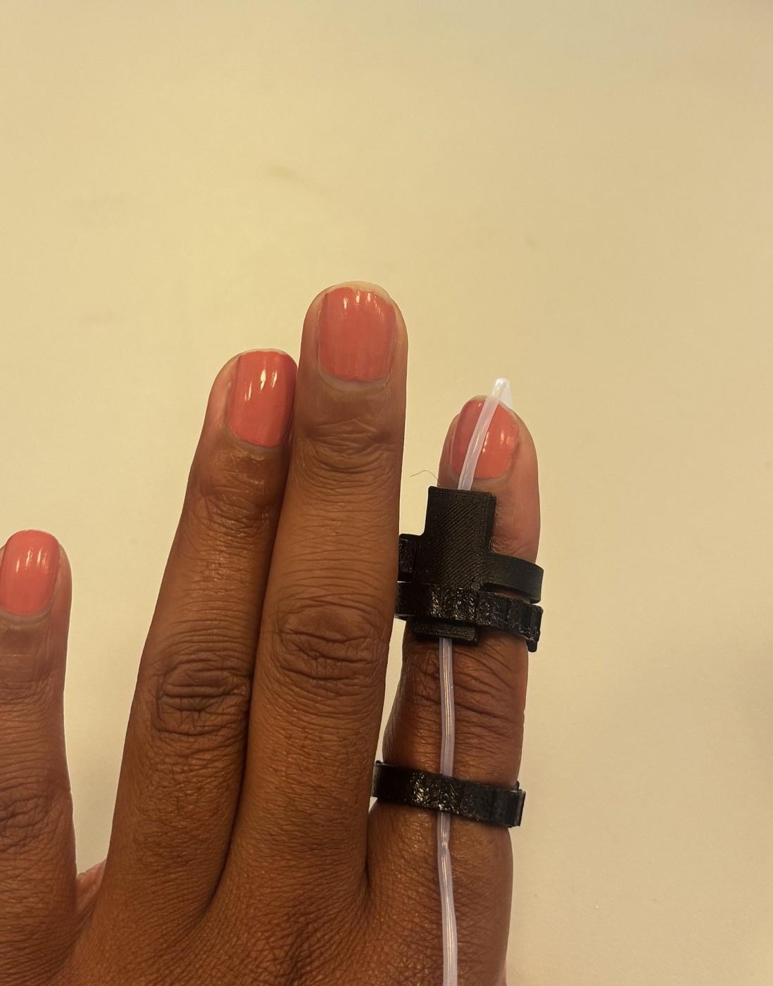
  1. Six early 3D-printed ring concepts arranged on a workbench
    01Ring concepts

    Printed rings tested simple ways to route the tendon around the finger.

  2. Early adjustable finger straps guiding tubing along a finger
    02Adjustable straps

    Straps made the finger interface easier to fit and reposition.

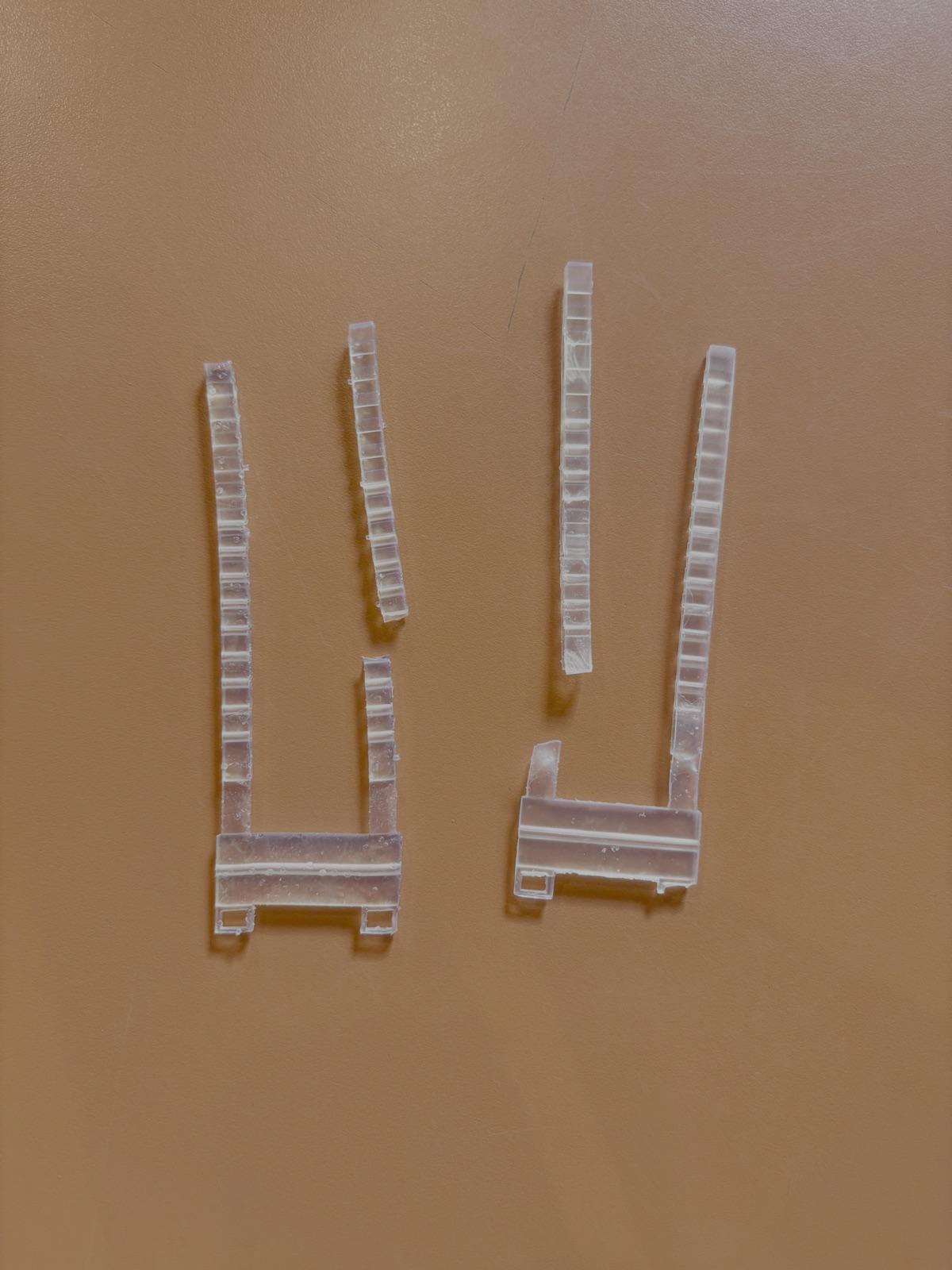
  3. Two failed transparent resin transmission pieces from the wearable prototype
    03Resin transmission

    The rigid resin path failed during development and was dropped.

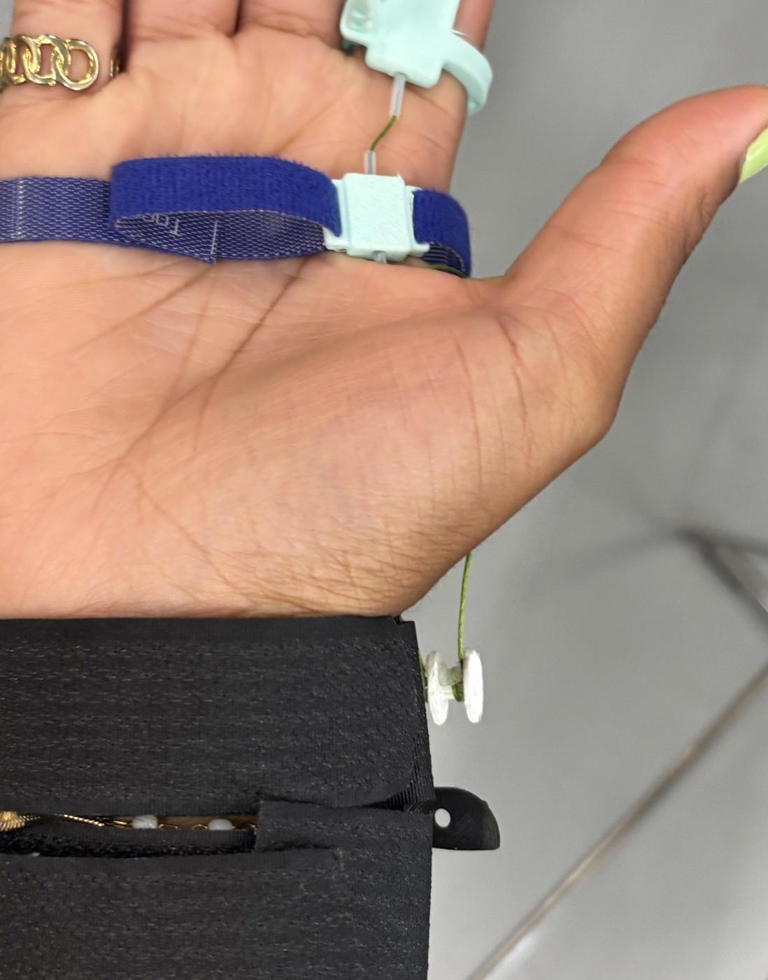
  4. Intermediate wearable interface using a Velcro strap and removable tendon guide
    04Velcro interface

    A removable guide made placement and rework faster between tests.

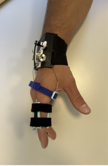
  5. Integrated tendon-driven finger actuator worn on a hand
    05Integrated wearable

    The final build joined the wrist unit, tendon path, and finger interface.

Working prototype

The final controller ran on the hand.

The encoder handled the fast motor loop while the camera measured what reached the finger. This run shows the reinforced wearable cycling with the acquisition overlay recording commanded and measured angle.

An eight-second on-hand run from the final 250:1 test series.

Wearable transfer

The wearable exposed the real constraint.

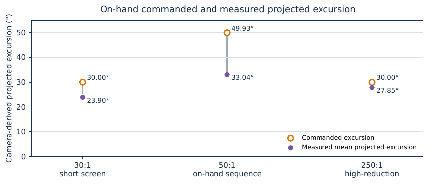
On-hand measurements fell below the commanded excursion even when the motor-side system continued to move. Slack, compliance, calibration, and the changing load path absorbed part of the motion. The wearable load path, rather than motor travel, became the limiting part of the system.

Comparison of commanded and camera-measured on-hand projected excursion across three configurations
Camera-side measurements separated commanded motion from the motion that reached the wearable load path.